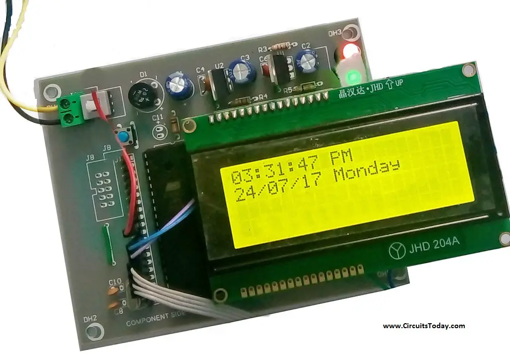
8051 Development board: So if you have this board it will be better so that you can easily upload the code by yourself. Seven Segment Display: In this project we are using six Common Anode Display. USB to UART converter: This is 9 Pin D type male Connector For RS232 O/p. I build this clock with AT89C2051, using timer to build sec,mn,hour i get a shift of 2mn within a laps of 21 days. Need to adjust the value of timer interrupt. It was a challenge for me,because i am working with PIC familly. In my case, not enough pins on this MCU to handle an RTC DS3231 to get a good time accuracy. The digital clocks are generally used to keep track of the time. It definitely displays the time, which can be easily read by anyone compared to conventional clocks. The device uses SST89E54RDA-40-C-PIE Microcontroller (MCU), a member of the FlashFlex family of 8-bit MCU that comes with 24/40 KByte of on-chip flash EEPROM program memory.
8051 Microcontroller Applications


The digital clocks are generally used to keep track of the time. It definitely displays the time, which can be easily read by anyone compared to conventional clocks. The device uses SST89E54RDA-40-C-PIE Microcontroller (MCU), a member of the FlashFlex family of 8-bit MCU that comes with 24/40 KByte of on-chip flash EEPROM program memory partitioned into two independent program memory blocks. It is 8051 compatible MCU with embedded SuperFlash memory. In addition, the device uses a seven-segment display to make the time visible for everyone.
- As mentioned already, the primary objective of the first laboratory is to design a digital clock on a 4 LED display using 8-bit 8051 microcontroller. The target system is expected to perform sixty seconds counts, i.e., for example counting from 00:00 to 00:59 in one second interval and repeating the counts one second after it reaches 00:59.
- Now the source code written in assembly, basically implements the I2C protocol. The assembly source written for Keil download here clock.asm and the direct hex file for programming the controller from here clock.hex. The schematic for the Digital clock is available in PDF format can be downloaded from here clock.pdf.
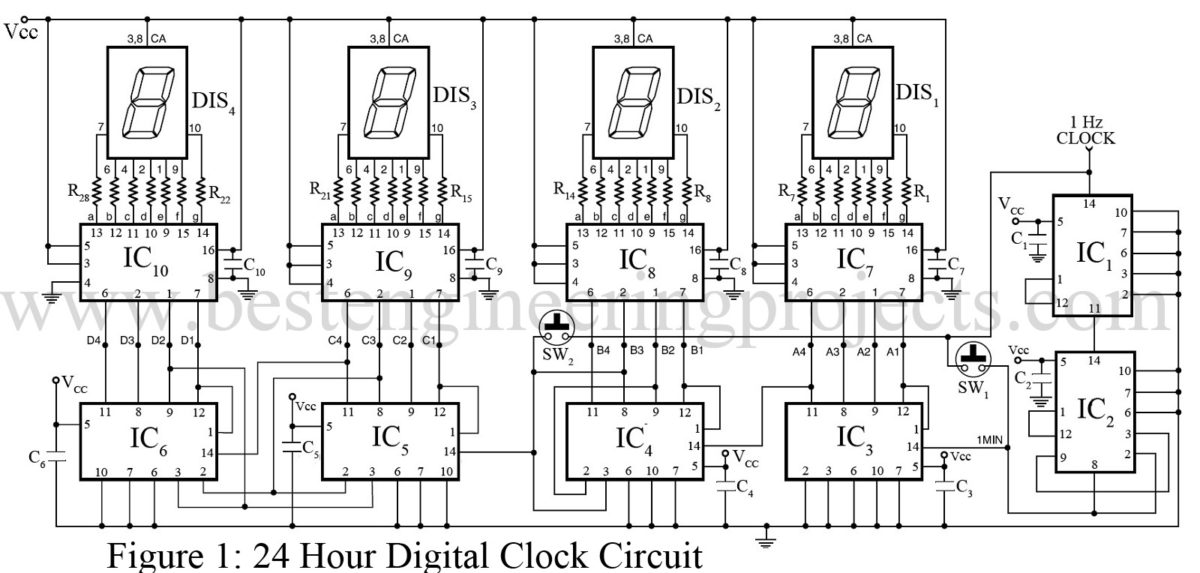
As soon as the VCC supply is provided to the circuit, the clock starts from 00:00. The time is displayed on four seven segments (in common anode configuration) by using the concept of multiplexing. This is achieved by using timer interrupt, which is configured to refresh seven segments. The segments are refreshed a couple of times in a second for simultaneous display. The clock runs with a delay of exactly one second. The data pins (a–h) of all the segments are interconnected and receive signal from port P2 of the microcontroller. The control or enable pins (common anode) are connected to pins 1-4 of port P1 (P1.0 – P1.3). The number on 4th segment (displaying the unit digit of second) is incremented once in a second as it goes from 0 to 9. The number on 3rd segment is incremented after every 10 seconds from 0 to 5. Thus, seconds are displayed varying from 00 to 59. The digit on the 2nd segment is changed after every 60 seconds from 0 to 9 and so on.


Program For Digital Clock Using 8051 Switch
The device can be seen anywhere in the world that may be noticed in the office or at home. This can be integrated to appliances for auxiliary feature and such applications may be observed in FM radios, televisions, ovens that has built in digital clocks.
Comments are closed.